


For most contractors, accurately connecting information from the office to the field, and from the field back to the model in the office, is an ongoing challenge. In the office, the building information modeling (BIM) or virtual design and construction (VDC) group can push information and models out to the field all day long, but if the crews in the field – the ones actually doing the work – don’t buy in to the process, these models are nowhere near as valuable as they could be. How do you create a workflow that establishes buy-in from everyone on your team?
Here is an overview of how Brasfield & Gorrie, a leading construction firm in Birmingham, Ala., has been able to get its project teams on board and establish a BIM plan that allows information to flow more easily from the office to the field and back.
1. Identify the Level of Detail
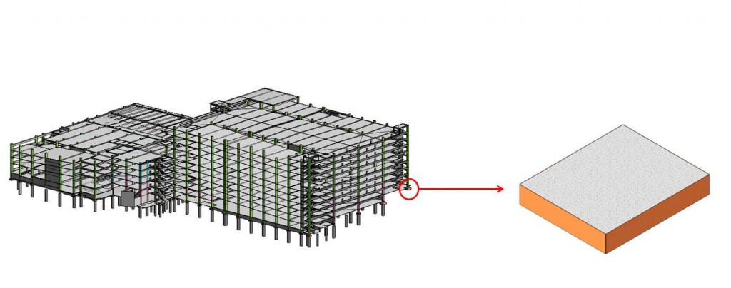
When developing models, the goal is to be as detailed and accurate as possible. On a large concrete pour, for example, this level of accuracy is evident in the type of information the firm extracts from the model such as surface area, contact area, and a visual representation of the formwork.
“We usually end up at a level of detail somewhere between three and four, depending on what we are really trying to achieve,” said Shawn Mancill, virtual design and construction coordinator for Brasfield & Gorrie. “Out of our reports, we try to get all of this information detailed out and organized in a manner that lets us send it to our pre-construction teams, who will be using the data.”
When modeling formwork for concrete footings, for example, the team provides a detailed formwork analysis that includes contact areas, sizes of components and other parameters so that estimators have a visual understanding of the contact area of a particular footing or object.
“This really helps us from a self-perform aspect when we are trying to get the most accurate cost data,” said Mancill. “Going through a detailed formwork analysis allows us to get more accurate in our material costs and labor projections.”
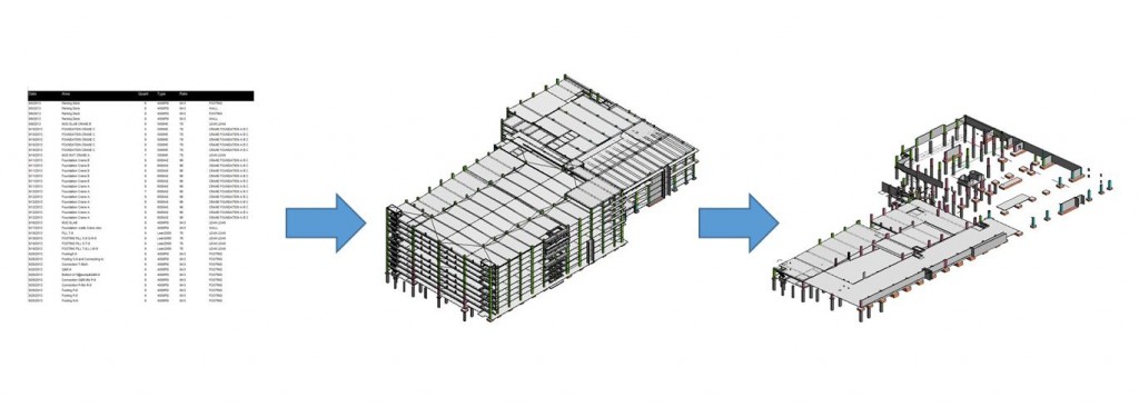
Through phasing and sequencing plans, the firm is able to break the models up, providing pour by pour quantities so that they can base their concrete truck orders on how much they are going to need for each pour. Another tool they use to save time and rework is elevated lift drawings.
“Most superintendents spend days or even weeks going through and cutting their own sections, trying to figure out elevations based on finished floor elevations,” said Mancill. “Using the model, we are able to go through and tag all of these elevations at the points they are needed at each pour break intersection and really become increasingly accurate with our pours and our construction process.”
2. Pull Information from the Field into the Model
Once a model goes into the field, the field engineer is responsible for laying it out and ensuring that the elevations are set correctly. Having an informed and correct model is a critical asset to the construction team.
An important part of validating these drawings and ensuring accuracy is incorporating information from the field back into the model to inform the rest of the construction process.
Progress updates help the firm determine where they are in construction based on how quantities are lining up – what’s poured today versus what is actually estimated for that particular bit of construction.
“What we’re finding is that we are actually able to validate our quantities with what is being poured,” said Mancill. “By validating those quantities, we’re validating our estimate and also creating a historical log that allows us to make predictions for similar projects in the future.”
3. Add Layout Points to the Model
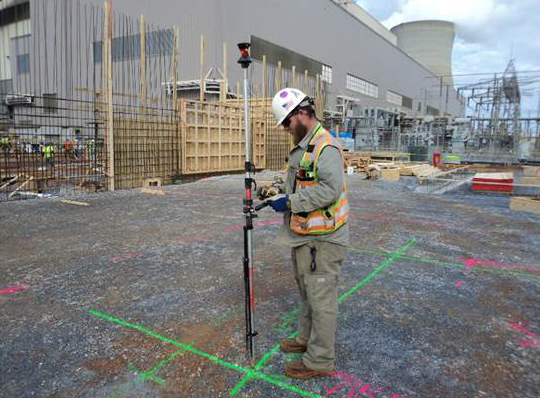
For Brasfield & Gorrie, all of this self-perform modeling has led to laying out a project directly from the model with Autodesk Point Layout (APL). The software allows the team to put points on a model and export them into a file that can be used with Leica Geosystems total stations to substantially improve accuracy and reduce rework in the field.
The team uses APL to layout footings and anchor bolts, and to go and back check anchor bolts and other items once they have been poured.
“If you get an anchor bolt wrong, especially when you have steel coming in and the holes don’t match the bolts, then you have a real problem,” said Mancill. “We’re able to go through, validate the anchor bolt placement, then take those anchor bolt placements and throw them back into the model. If there are any major adjustments that the steel fabricator needs to know about, that can be transmitted to them to prevent problems with this layout process.”
4. Verify with Laser Scanning
Within the last few years, Brasfield & Gorrie has begun using laser scanning to document and verify existing conditions accurately. The team’s first scanning project was at a local hospital that is under construction.
“We began construction on this hospital about eight years ago and were coming back to finish the building,” said Russ Gibbs, regional director of virtual design and construction at Brasfield & Gorrie. “We needed to accurately document and verify the skin condition around the building to share this information with subcontractors.”
Working in partnership with Auburn University and Leica Geosystems, the firm used a combination of laser scanning and photogrammetry captured with an unmanned aircraft system (UAS) in a test project to evaluate how the technology could be used to document the exact conditions of the existing building’s façade and create a model over the scan.
“With this information, we have a point that we can lay out and go back to and a link to the image so we can verify the façade to make sure it doesn’t have cracks or leaks,” said Gibbs. “Laser scanning allowed us the opportunity to document the as-built condition to be able to provide the information accurately.”
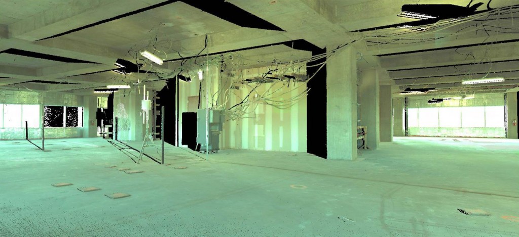
The firm is also using laser scanning on the interior of the building to show tie-ins to all of the gas and piping in the shaft wall of the existing unfinished levels for overhead EDP coordination.
“We have modeled based on structural drawings – the original structural drawings – so we have a Revit model, but laser scanning allowed us to come in and verify that Revit model and see beam sizes and column locations to see if we were right on or not,” said Gibbs.
As a result, the team found a few discrepancies between what was on the drawings versus what was built, and they were able to make adjustments to avoid additional rework.
“Something that we all kind of take for granted is, ‘Hey, let’s just run this pipe. Once it ties in, we’ll figure it out,’ which causes issues for us in a lot of renovation projects,” said Gibbs. “A scan gives us the right elevation to tie-in correctly and avoids a lot of headaches down the road.”

Note: This article is based on the webinar, The Lifecycle of a Model, presented by Leica Geosystems and Brasfield & Gorrie in March 2014. To learn more about connecting models to field work, download the webinar transcript.