Most of the methods used today for conducting slab flatness analysis are manual and labor intensive. Floor flatness/floor levelness (FF/FL), a commonly used method, requires the creation of a grid on the concrete slab following a set of specifications before taking manual readings. Contractors that use the ASTM E1155 standard method for determining floor flatness (FF) and floor levelness (FL) numbers typically take a measurement every foot along the grid lines. Using this method, even small projects often require a substantial amount of time to complete the data collection and analysis. Recently, however, contractors have begun to discover a new way to save a substantial amount of time and money on their projects: laser scanning.
For all kinds of projects – from renovations to new construction – laser scanning collects rich, complete and highly accurate as-built data to validate existing building documentation to ensure that new construction matches the as-design models, minimizing the risk of change orders. Laser scanning for floor flatness dramatically improves workflows and provides more effective deliverables.
Improved Data Collection and Elevation Mapping
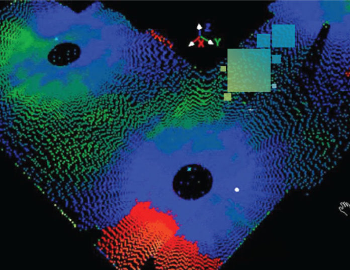
Since scanning captures so many points, users can simply color the cloud in respect to elevation and it will quickly become obvious if there are high or low points in the concrete pour. The extent of the high and low areas can be established and discrete points can be applied to the boundaries.
Because these points maintain their coordinates, they can be uploaded to a total station or multistation and laid out in the field to visually communicate to project stakeholders. The actual volume of cut/fill material can also be computed utilizing the laser scan data.
Faster ASTM E1155 (FF/FL) Analysis
In this analysis, scan data is utilized along with “points on a grid” functionality in Leica Cloudworx for AutoCAD or in Cyclone Survey. These solutions allow concrete contractors to locate gridlines to meet ASTM requirements and apply the elevations from the point cloud data. This data can then be exported to the Leica FF/FL calculator for analysis based on the project specifications.
The scan data can also be used to create a solid surface that can then be compared with the point cloud for fast and accurate cut/fill calculations.
With laser scanning, processes that once took several days can be reduced to a matter of hours while yielding far more accurate data—and better information for your project team.
Watch this video to see how 3D laser scanning can be used to analyze slab flatness with Leica Cyclone Survey:
To learn more about laser scanning for concrete slab flatness analysis, contact us for a consultation.


