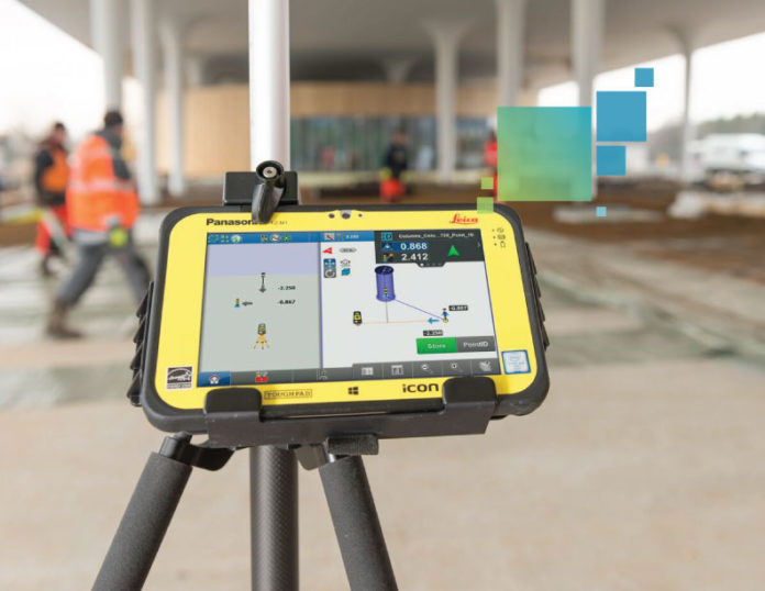
Getting started with BIM and digital layout can seem like a monumental task if you don’t know where to start. The first step is understanding the “lay of the land” – what are the parts and pieces, and how do they fit into your business. From there, it is much easier to strategically choose a starting point that will yield the best return on the investment.
A good place to begin is with an overview of the basic equipment used for digital layout from CAD or BIM and how they work together. Three key pieces of hardware are used for digital construction layout are 1) the field controller, 2) the sensor or instrument, and 3) the prism.
Basic BIM Hardware
The field controller
This handheld device runs field software that controls the sensor or instrument. It is typically a sealed, extremely tough version of a Windows tablet enclosed in a ruggedized case so it can survive the harsh conditions on construction sites without getting broken. Look for models that feature an extra-long range Bluetooth range of about 1,200 feet (although this range varies by controller) to remotely control instruments.
The sensor/instrument
Unlike the error-prone traditional methods of tape measures, string and plumb bobs, modern total stations and laser distance meters enable contractors to measure angles and distances with precision. New technology such as 3D laser distance meters can be used to streamline the layout of new interior construction such as mechanical, electrical and plumbing (MEP) and wall partitions. Recent innovations such as the multistation effortlessly integrate laser scanning capabilities with total station measurement for as-builting, construction layout and quality assurance checks.
Prism
A prism is used to reflect an infrared or red laser beam from the sensor or instrument. Prisms are most commonly used on a “prism pole” to give them height when measuring a point on the ground or floor.
How These BIM Tools Work Together
Most contractors use a 3D model to coordinate between disciplines – i.e. mechanical, structural and plumbing – so clashes do not occur in the field. This coordinated data can be used directly in the field by adding layout points either to the model or on 2D construction documents. The data is then handed off to the field controller, which is wirelessly connected to the sensor. The instrument is oriented to align the layout data with the jobsite. From there, contractors simply start “shooting points” to replicate the accuracy of BIM in the field.
Once work is in place, the layout points can be “back checked” to validate that the as-built (real world) matches the as-designed (model) with real time delta reporting. When deviations are identified, the as-built points can be brought back into to the model so the impact of the deviation can be evaluated by the project team and corrective actions can be planned if needed.
This insight is invaluable for contractors. It’s like having a crystal ball that predicts constructability issues and allows them to be corrected digitally before they become change orders and schedule delays.


