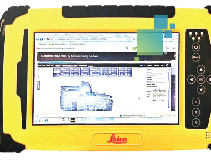
If your BIM data has already been prepped for field layout, you’re ready for the next step: taking it into the field. Armed with BIM layout points, plan underlays and reference models, you are now ready to shoot points on the jobsite that replicate the accuracy of BIM in the office.
RELATED: BIM 101: How to Prep Model Data for Field Layout
Getting Oriented: Aligning the Jobsite with the Model
Once in the field, the first step is to set up your instrument and make sure the construction site aligns with the model. Start by planning out where the total station, multistation or laser distance meter will be positioned to shoot layout points. The location should also be level, away from major construction traffic and provide a clear line of sight to at least two control points on the field controller and physically onsite.
Once the total station, multistation or laser distance meter is set up, the data collector needs to be connected to the instrument via wireless communication, such as WiFi or Bluetooth, so the two devices can communicate.
Next, it’s time to align model data with the onsite control points. This is accomplished by selecting the first control point on the model and measuring it in the field. A second control point on the model should then be selected and measured in the field to provide direction. Matching up the two control points from the model in the field will orient the instrument so you can flawlessly start shooting layout points with ease.
Paint by Numbers: Shooting BIM Points in the Field
Once your instrument is oriented, select the first point to lay out. If laser mode (a visible red laser) is being used, the robot will automatically turn and indicate the exact point. If infrared laser with a prism is being used, the field controller software will guide you to the point with directions such as “left,” “right,” “closer,” “back,” etc., until you arrive at the exact point. Continue this process until all reachable points have been shot and marked.
To move the robot to the next location to continue shooting points, identify two points that will be used to reorient the instrument. These can be previously measured points, or you can shoot two new points exclusively for reorienting. Move the instrument to the new location, level and reorient by selecting the first control and measuring. Continue with a second control point. You should now be oriented and ready to lay out more points.
Robotic total station layout is a natural extension of BIM. It is a very efficient process that leverages highly accurate coordinated models for layout. Better data means better results. Robotic layout is also much more efficient than manual total station layout – one-man operation means that your labor is cut in half or more, which can increase your point layout productivity by an average of 25 percent.
Contact us with your field layout questions, and our knowledgeable experts will be happy to assist you.


