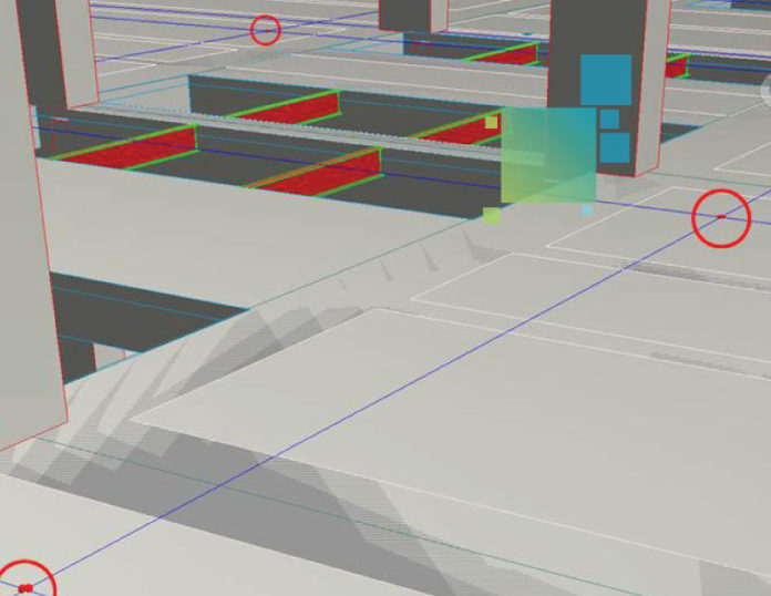
If your project is working with highly accurate models in the office, that’s a good start for BIM. In many cases, however, the model data isn’t being used directly in the field. At best, this information gap drives up project risks; at worst, it results in errors and delays that can derail the entire construction schedule and budget and potentially lead to litigation. Fortunately, these problems can be easily solved by enriching the model with construction layout points.
Once you’ve merged models from all disciplines and completed pre-construction coordination (clash detection), the next step is to prepare the construction layout points in the model to be handed off to the field.
Identify and Prep Construction Layout Points
Begin the process by determining which elements need construction layout points. Then identify at least two “control points” so the digital data can be oriented to the physical building in the field. The “control points” must be marked in the field and in the model so the coordinates can be easily aligned.
It’s important to note that construction layout doesn’t have to start with a model from a BIM creation tool such as Autodesk Revit. Projects such as residential concrete foundations can begin with paper drawings or 2D CAD drawings. If starting with paper, you can easily sketch the foundation directly in field software such as Leica iCON Build and add layout points directly in the field software. This type of digital layout is an excellent on-ramp into the BIM process. If you’re using a CAD file, layout points can be created using software such as MS Point Prep for highly accurate replication in the field.
Go here to learn how to get started with digital layout.
However, the most accurate way to add layout points is directly on a model using a tool such as Autodesk Point Layout. Points can be manually added, or the process can be automated by applying layout points to Revit families. For example, if layout points are added to a concrete pile cap family, all of the pile caps will automatically get layout points.
Hand Off the Layout Points to the Field Team
Once the layout points are prepared, the data is ready to be handed to the field team. The next step in the data prep process is to export the points in an ASCII file format (.txt or .csv) and a plan underlay in DXF format. If your field team views reference models in the field, determine the viewer they are using and the file format they need for model viewing.
Once The DXF plan is imported, it will show up as an underlay to your points, which can be turned on or off as needed. For example, if you are laying out column locations, you would see a plan view of the columns with points at all the columns to identify your location in the field. This helps with orientation and provides context in the field.
Using high-accuracy tools such as multistations or total stations combined with intelligent software to apply construction layout points to the model and then transferring those points to the jobsite creates a “paint by number” plan for the contractors and installers. Enriching construction with high levels of accuracy streamlines processes, reduces the risk of errors, and improves predictability.
If you need more tips on prepping data for construction layout, please contact us. Our knowledgeable BIM experts will be happy to assist you.


