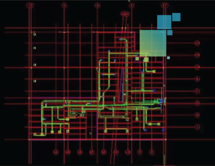
No matter where you are in your BIM adoption process – whether you are just getting started with digital layout or already using advanced 3D workflows on every jobsite – there are field tools that can enrich your workflows and help you improve your accuracy, efficiency and overall productivity. Most mechanical, electrical and plumbing contractors begin experimenting with BIM by using paper or CAD files for MEP digital layout. MEP layout requires accurate information throughout the entire process to avoid expensive rework, so having the ability to quickly and easily add construction layout points to your project is critical in the field, as well as in standalone CAD environments. Here are three common MEP workflow challenges and the basic field tools that can help you overcome them.
Challenge#1: Adding Construction Layout Points to Models
Robotic total stations are easy to use, highly accurate, and can enrich your construction layout process by accurately replicating coordinated MEP models and drawings from the office into the field.
To streamline the BIM-based layout process and add construction layout points to your models, look for high-precision robotic total stations and intuitive field software packages that are only easy to use but also only require a single person to operate in the field, which will save you time and money. Some solutions even offer capabilities such as advanced tracking.
For even more versatility, consider using a scanning total station (also called a multistation). These multipurpose tools enable you to capture preconstruction as-built point cloud data with a single instrument and replicate highly accurate BIM layout points in the field. They also you to capture high-definition point clouds for quality assurance comparisons with as-designed models in the 3D BIM lifecycle. Any deviations are identified in real-time and can be easily scanned with the same device, substantially reducing post-processing and rework.
The integration of intelligent and easy-to-use layout software with any of these tools will further streamline your BIM-based layout process.
Challenge #2: Adding Layout Points to CAD Drawings
Adding construction layout points to CAD drawings in the office or in the field is the next level of BIM adoption and requires the addition of construction field software to your robotic total station.
With this combination, you can reduce errors and achieve a higher level of project outcome predictability faster and with fewer people in the field compared to using tape or manual total stations.
Look for point prep software that helps you prepare all of the field data you’ll need on the jobsite while you are still in the office and makes it easy to create coordinates, input plan data from paper plans, create point patterns, compute offset points, create DTM models and prepare as-built drawings.
The software should also seamlessly synch with your layout software so that your points and drawing data can be used at the jobsite for layout.
Challenge #3: Interior Layout with a Red Laser
For streamlined interior layout in the field or in a standalone CAD environment, 3D laser measurement tools can help you quickly capture and record interior as-built information – including areas, inclinations, and angles – no matter how complex or large the room.
Complete rooms, walls, windows, stairs and structural connections can be measured from a single location, and built-in options allow you to easily establish plumb, create level reference points, and precisely transfer offsets or locations. Some instruments even allow you to use streaming video and your fingertip to guide the red laser to each point.
For interior layout in the field, software developed specifically for MEP layout can make it easy to layout points on floors, walls, ceilings and pipe penetrations with a simple laser dot. Some software will automatically iterate several measurements to determine where the true surface is and adjust the layout location automatically. For example, MicroSurvey Layout has an MEP module that features a tool called “auto-locate.” You simply click the menu option and watch the instrument work. Within the software, you can view the space in 3D and confirm that the locations are correct as the instrument takes measurements. Then, using the laser dot from the 3D laser measurement tool or total station, you can mark the point on the wall or floor and be confident that it’s in the right place.
For layout in a standalone CAD environment, look for software that allows you to easily prepare layout and as-built work and then create professional CAD drawings.
To learn more about these tools and how they can provide solutions to common BIM challenges, please contact us. We’ll help you find the best solution for your next project.


